PARTNER-COORDINATED PROCESS
5-Axis CNC Machining Services
Some parts have faces at an angle to one another, undercuts or a contoured surface that a three-axis setup can only reach by re-fixturing. We review those parts for a five-axis route arranged through our partner factories.
Updated · Alloyvanta editorial team
A coordinated route, not our own machines
Let us be direct about what this page describes. Five-axis machining is a partner-coordinated process: it is arranged for your project through our partner factory network, alongside our six in-house services. We coordinate the enquiry, the drawing review, the production and the inspection scope, and we are responsible to you for the result. We are not describing equipment in our own workshop, and the parameters below are planning references rather than measured limits of a specific machine.
Our own in-house services cover CNC machining, milling, turning, sheet metal fabrication, laser cutting and metal prototyping. Specialist routes including five-axis work are grouped separately under partner-coordinated processes, so you can always see which is which. Availability and the achievable combination of size, tolerance and material are confirmed for each project.
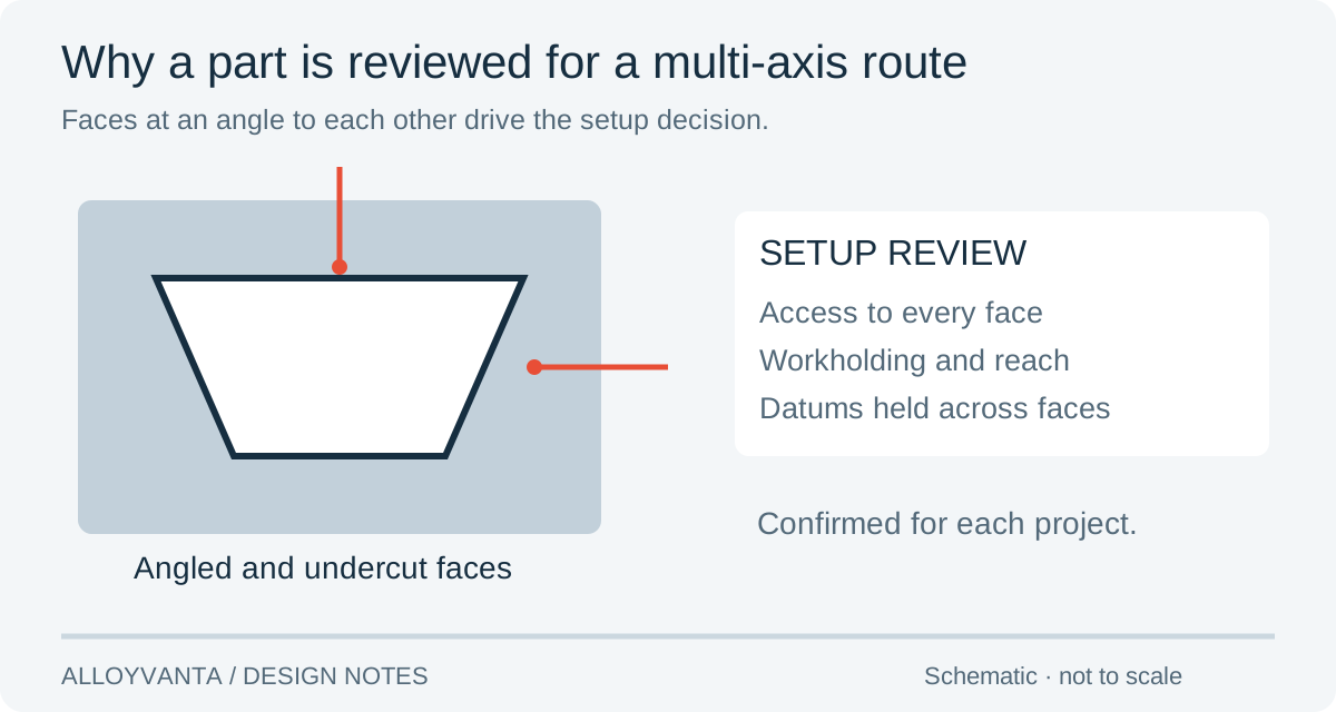
When a part is worth reviewing for five axes
The question is not whether five axes are impressive but whether your part needs them. Three signs point that way. First, faces at an angle to one another that carry related features: every re-fixturing step re-establishes that relationship, and each one is an opportunity to lose it. Second, undercuts or geometry a vertical tool cannot reach. Third, a continuously contoured surface, where a multi-axis path can hold the tool at a more consistent angle to the surface.
A part with features on one or two parallel faces usually does not need it. In that case CNC milling on a three- or four-axis setup is the more straightforward route, and the general tolerance reference for it is ±0.1 mm against ±0.05 mm for the five-axis route. Both are general references that apply where no individual tolerance is stated. Critical features require an individual drawing callout.
| Characteristic | Why it points at a multi-axis route | What to send |
|---|---|---|
| Faces at an angle to each other | Features stay related without re-fixturing | The model, plus which faces share a datum |
| Undercuts or restricted access | A vertical tool cannot reach the feature | A view or note marking the feature |
| Contoured surfaces | Tool angle can be held more consistently | The surface definition in the model |
| Tight relationships across faces | Each additional setup adds variation | Individual tolerances on those dimensions |
| Large or awkward workholding | Access and support are decided together | Overall size and any clamping restriction |
Planning references for the five-axis route
These are the published references for this route in our process parameter library. Read them as a starting point for a drawing discussion. A value here does not mean every feature on your part can be produced to it, and a size limit is not a promise that a part of that size can also hold the tightest tolerance in the table.
| Parameter | Reference / planning value | Application |
|---|---|---|
| Maximum part | 4000 × 1500 × 600 mm | Confirm multi-side access and workholding. |
| Minimum part | 5 × 5 × 5 mm | — |
| Minimum feature | 0.5 mm | Width or depth, subject to geometry. |
| Unreamed hole diameters | Ø1–40 mm | — |
| Shaft diameters | Ø2–300 mm | Design guidance within a multi-axis setup. |
| Thread sizes | M2–M24 | — |
| Engraved text | Height ≥1.5 mm; depth 0.5 mm | — |
Workholding is the constraint people underestimate. A part can be inside the maximum envelope of 4000 × 1500 × 600 mm and still be difficult, because it has to be held rigidly while tools reach several faces. Tell us where the part may be clamped and which surfaces must stay unmarked, and that gets reviewed with the geometry rather than discovered during production.
Prepare the drawing for a multi-axis part
Multi-axis geometry makes the drawing more important, not less. Identify the datums and say which features must hold their position relative to them, because that relationship is the reason for choosing the route. Give individual tolerances to the dimensions that carry the function and leave the rest under the general reference. Where a surface has a functional requirement, state it as a parameter and a limit using the surface roughness reference.
Send the current STEP model and a PDF drawing on the same revision, as the CAD preparation checklist sets out; for several parts together, the assembly drawing guide covers keeping the file set consistent. Choose the material with its condition attached — the 6061 and 7075 comparison works through an aluminium decision, and the material library covers the other families. Agree the inspection scope in the quality discussion before production, since features that cross several faces are the ones worth measuring.
Ask about a five-axis part
Send the model, the features that must stay related to one another, the material and the quantity. We will confirm whether the part suits this route or is better made on another, and say plainly which of our services or partner processes is involved. Quotation within 24 hours. First response within 12 hours. Our team is available 24/7.
Production orders start at 100 pieces per part number, counted separately for each part. Prototypes and sample parts are quoted from a single piece. Design-only projects are quoted separately.
Frequently asked questions
Does Alloyvanta own five-axis machines?
No. Five-axis machining is a partner-coordinated process arranged through our partner factory network. Our six in-house services are CNC machining, milling, turning, sheet metal fabrication, laser cutting and metal prototyping.
Is a five-axis part always more expensive?
Not necessarily. Fewer setups can offset a higher machine rate, particularly where features on several faces must stay related. A part that suits a three-axis setup is usually quoted more economically there.
Can you hold the tightest tolerance across the full size range?
No. Treat the size and tolerance references as separate planning values. The achievable combination for your part depends on the geometry, material and workholding, and is confirmed in the quotation.