Ra and Rz answer different questions
Ra is the arithmetic mean deviation of the profile: the average of the absolute height values along the measured profile. Because it is an average, it is stable — Evident's parameter reference notes that Ra “provides for stable results as the parameter is not significantly influenced by scratches, contamination, and measurement noise”. That stability is exactly why Ra alone can pass a surface that has one defect you care about.
Rz is the sum of the maximum peak height and the maximum valley depth within the reference length. The same reference notes the opposite property: maximum height “is significantly influenced by scratches, contamination, and measurement noise”. If an isolated scratch or a single deep valley matters to your part — a sealing face, for example — Rz or another peak-based parameter describes it where Ra will average it away.
| Ra (μm) | Ra (μin, converted) | Commonly associated with |
|---|---|---|
| 0.05 | 2 | Specialist fine-finishing routes |
| 0.1 | 4 | Ground and lapped surfaces |
| 0.4 | 16 | Fine finishing operations |
| 0.8 | 31 | Finish machining of suitable features |
| 1.6 | 63 | Commonly specified functional surfaces |
| 3.2 | 126 | General machined surfaces |
| 6.3 | 248 | Coarser machined and as-built surfaces |
| 12.5 | 492 | As-cast and unfinished surfaces |
The microinch column is an arithmetic unit conversion of the left-hand column, rounded to the nearest whole microinch. It is not a claim about what any particular process achieves. The right-hand column indicates where such a value is typically discussed, not a guaranteed result.
Make the drawing callout measurable
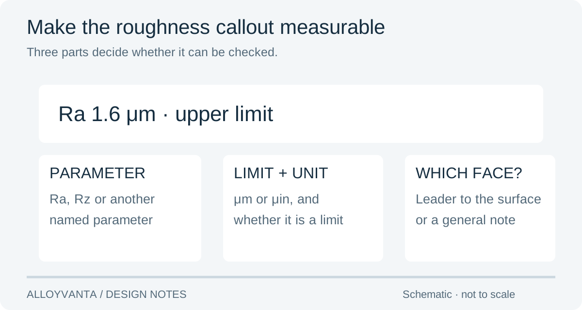
A note reading “smooth finish” cannot be inspected and cannot be quoted. Three things make a roughness requirement checkable: the parameter, the limit with its unit, and which surface it applies to. Add whether the value is an upper limit, and whether it applies before or after any surface treatment, since plating and anodizing change the surface you are measuring.
Drawing indications for surface texture were previously given in ISO 1302, and the parameter definitions in ISO 4287, with sampling rules in ISO 4288. Those profile standards have been brought together into the three-part ISO 21920 series: Part 1 covers drawing indication, Part 2 the terms, definitions and parameters, and Part 3 the default specifications. Pre-existing drawings still carry the requirements they were drawn against, so identify which convention a drawing follows rather than assuming the newest one.
| Element | Why it is needed | Example of an incomplete note |
|---|---|---|
| Parameter | Ra and Rz describe different things | “Ra/Rz 1.6” — two parameters, one value |
| Limit and unit | μm and μin differ by a factor of about 39 | “Roughness 32” — unit missing |
| Which surface | A general note applies to everything | Leader line pointing at nothing specific |
| Upper limit or range | Decides how a measurement is judged | “Ra 1.6 typical” |
| Before or after finishing | Coating changes the measured surface | No statement, part is anodized |
| Measurement direction | Machined surfaces are directional | No lay indication on a turned face |
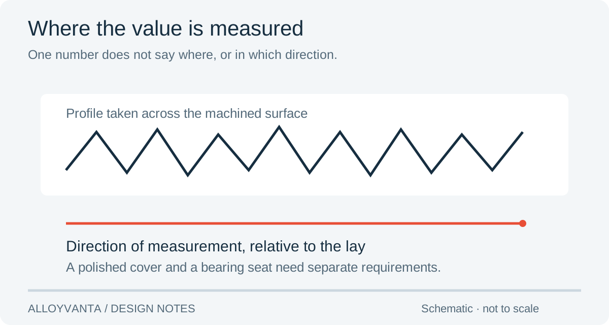
One number does not say where, or in which direction
A machined surface is not the same in every direction. Turning and milling leave a directional pattern, so a profile measured across the tool marks and one measured along them can give different values on the same part. Where that matters, state the direction or the lay in the requirement rather than leaving it to whoever holds the instrument.
The evaluation length matters too, and this is where ISO 21920 changed something substantive. Under the earlier convention, most parameters were calculated per sampling length and averaged. In ISO 21920, parameters are defined on the evaluation length: as Digital Surf's guide puts it, “there will be only one Ra (or Rq) value calculated on the profile”, with Rp, Rv and Rz still averaged to reduce the influence of outliers. The term “sampling length” also becomes “section length”. The definitions of Ra, Rq, Rsk, Rku and Rt themselves are unchanged.
The practical consequence is narrow but real: if a supplier and a customer measure the same surface under different conventions, they can report different numbers without either being wrong. For a critical surface, agree the parameter, the length and the direction, and record them with the inspection requirements rather than settling them after delivery.
Published route references, and what they are not
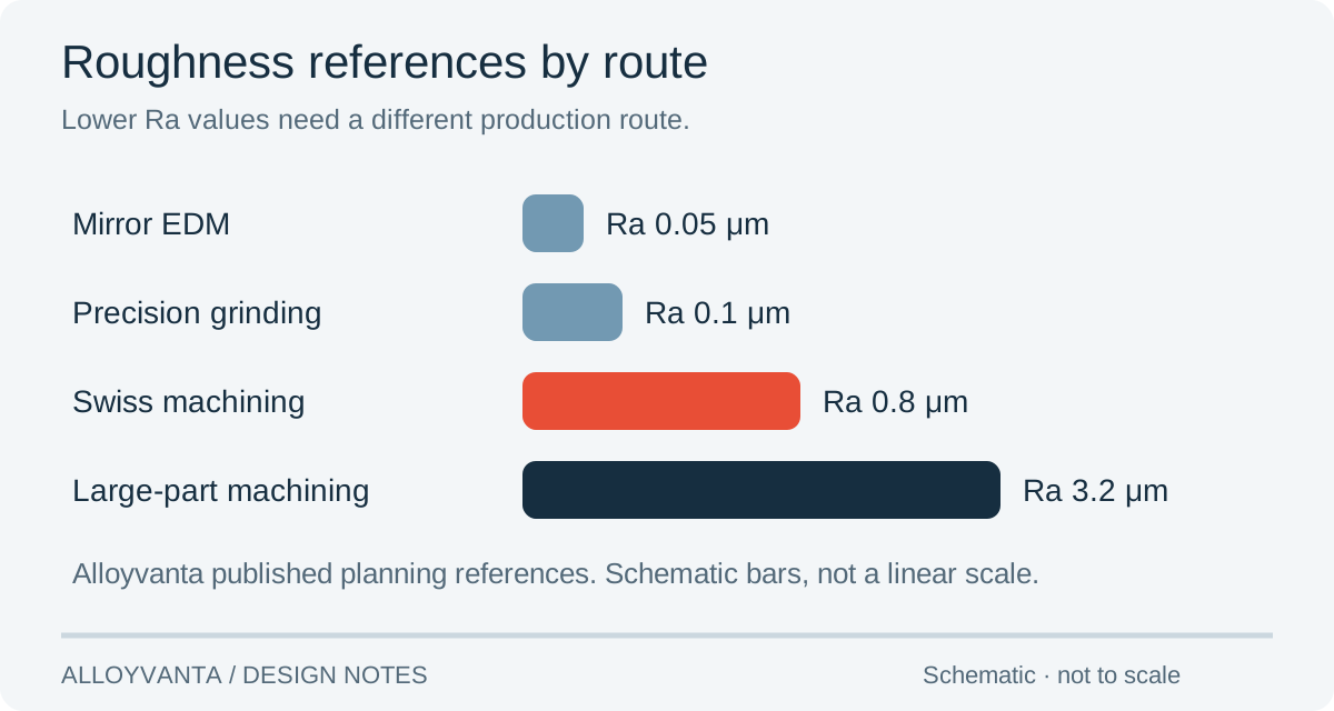
The values below are the surface roughness references published in our process parameter library. Every one of them belongs to a partner-coordinated specialist route: none of our six in-house services publishes a roughness figure, because the achievable surface depends on the material, the feature and the setup rather than on the process name alone.
| Process | Production route | Published reference |
|---|---|---|
| Mirror EDM | Partner-coordinated process | Ra 0.05 μm |
| Precision Grinding | Partner-coordinated process | Ra 0.1 μm |
| Swiss CNC Machining | Partner-coordinated process | Ra 0.8 μm |
| Large-Part CNC Machining | Partner-coordinated process | Ra 3.2 / 0.8 μm |
| Metal 3D Printing (SLM) | Partner-coordinated process | Ra 3.2–6.3 μm |
| Sand Casting | Partner-coordinated process | Ra 12.8–50 μm |
Read these as planning references for a conversation, not as commitments for a specific part. A value published for a specialist route says what that route is typically discussed against; it does not mean every feature on your part can be produced to it, and it does not mean we hold that figure on our own machines. Availability and the achievable combination are confirmed for each project.
Where a finer surface is genuinely required, it is usually reached by adding an operation — grinding, polishing or a specialist finishing route — rather than by tightening a general note on a machining drawing. Identify the specific faces that need it, and the ones that do not.
Put the requirement into your enquiry
Mark the functional surfaces on the drawing and give each one a parameter, a limit and a unit. Leave the remaining surfaces under the general condition so the effort goes where the function is. Say whether you need a measurement record with the parts, and on which features.
Then carry it into the route. For diameters, bores and sealing faces, see CNC turning; for pockets and machined faces, CNC milling; and for how the overall route is chosen, the machining overview. If the surface requirement exists for appearance rather than function, the surface finish library is the better starting point, and the finish checklist covers what to specify.
Frequently asked questions
Is Ra 1.6 μm the same as 63 μin?
1.6 μm converts to approximately 63 μin, so the two are the same requirement expressed in different units. Always state the unit in the callout, because the numbers differ by a factor of about 39 and a bare number is ambiguous.
Can I just write “polished” on the drawing?
That describes an intent, not a requirement that can be measured or quoted. Give the parameter, the limit and the surface it applies to, and state whether it applies before or after any coating.
Does a lower Ra value cost more?
Usually, because a finer surface is often reached by adding an operation rather than by machining more carefully. The cost comes from the extra process step, so apply the requirement only to the surfaces that need it.
Technical references
Method. Parameter definitions and the ISO 21920 changes are quoted from the references listed above. Route reference values are read directly from the approved process parameter library on this website, with their production route shown; they are planning references, not measured results for a specific part. Microinch values are arithmetic conversions of the micrometre column, rounded to the nearest whole microinch. Diagrams are schematic and not to scale.