DXF with closed, non-duplicated profiles
Include the requirement or identify it as an open question for the project review.
CAPABILITIES
Our laser cutting service turns a two-dimensional profile into a flat metal part. The cutting file, material thickness and edge condition are confirmed together before production starts.
A focused laser follows the cutting profile. Thickness, narrow bridges and small holes influence whether the drawing suits this route.
Typical part types: Flat brackets, plates and mounting profiles.
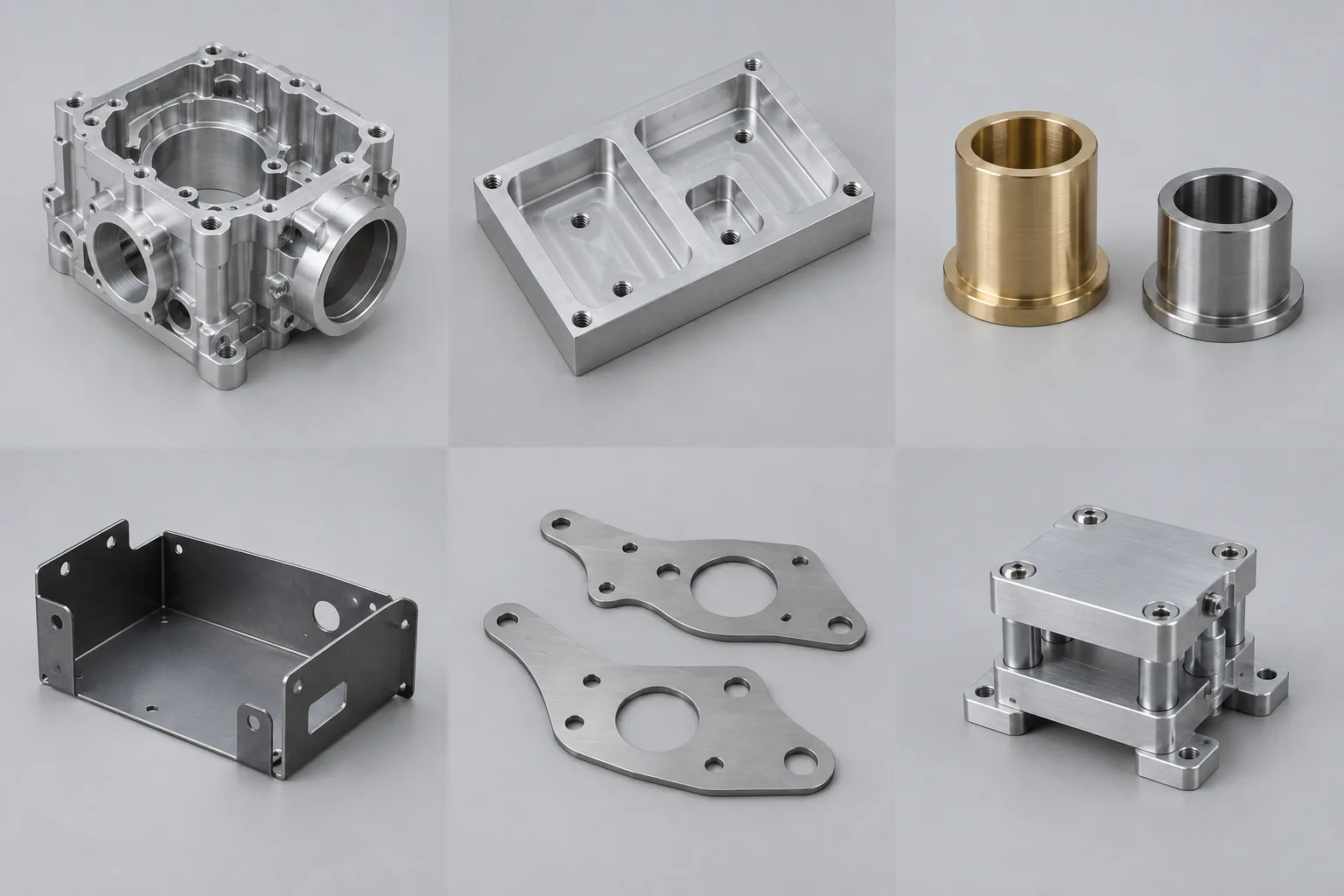
A laser follows the geometry you supply, so the file is the specification. Export the profile at full scale, close every outline, and remove duplicated or overlapping lines: a doubled contour can be read as two cuts in the same place. State the units, because the same numbers describe very different parts in millimetres and inches.
Keep cut, etch and bend information on separate layers, or add a drawing note that says which is which. Otherwise an intended surface mark can be interpreted as a through-cut. If the flat part will be folded afterwards, identify the bend lines and the finished direction rather than leaving them inside the cut geometry.
| Material | Thickness reference | What to confirm with the drawing |
|---|---|---|
| Carbon steel | <25 mm | Grade, surface condition and whether a cut edge is acceptable as-cut |
| Stainless steel | <15 mm | Grade, visible faces and any passivation requirement |
| Aluminum | <15 mm | Alloy, temper and the intended finish |
| Copper | <12.7 mm | Whether the profile suits a cutting route at that thickness |
| Maximum panel | 1500 × 3000 mm | Nesting, grain direction and how the part is separated |
Three figures get confused in laser cutting enquiries. Positioning accuracy (±0.10 mm) and repeatability (±0.05 mm) describe machine movement. The dimensional reference we plan flat parts against is ±0.2 mm, a general reference of ISO 2768-c. A machine specification is not a promise about your part.
Kerf width and the heat-affected edge depend on the material, thickness and cutting parameters, so we confirm them for the job instead of publishing one number for every material. If a hole or a narrow bridge is close to the thickness of the sheet, mark it as a feature to review. Small holes and thin webs are where a cutting route most often needs a different answer.
State whether the cut edge is acceptable as produced, needs deburring, or has to be clean enough to handle or paint. If the part is folded, welded or assembled afterwards, the flat profile is only one step: bring it together with sheet metal fabrication so the bend allowance and the finished dimensions are reviewed as one part. Our sheet metal gauge reference explains why a gauge number alone is not a thickness.
For coating or plating, identify the visible faces and any masked areas in the surface finish requirement, and say whether your dimensions apply before or after finishing. A cut part that also needs machined features, threads or tight bores usually belongs on a combined route with CNC machining.
Send the DXF, the material and thickness, the quantity and any edge or finishing requirement. Add a PDF or marked-up view when the drawing carries notes the geometry cannot show, and choose the grade from the material library if it is not already fixed. Quotation within 24 hours. First response within 12 hours. Our team is available 24/7.
PREPARE YOUR PROJECT
Include the requirement or identify it as an open question for the project review.
Include the requirement or identify it as an open question for the project review.
Include the requirement or identify it as an open question for the project review.
Identify the application before choosing a grade. Discuss material condition, critical surfaces and whether dimensions apply before or after finishing.
Browse the material libraryYOUR QUESTIONS, ANSWERED
Find practical answers before starting a project.
Use separate layers or a clear drawing note to distinguish cut edges from marking. Otherwise an intended surface mark can be interpreted as a through-cut.
Choose “Help me choose” in the inquiry. Explain the application and environment so the options can be reviewed against the function of the part.
We provide a quotation within 24 hours. Estimated delivery is 3–7 days after the order, drawings and required upfront payment are all confirmed: full payment for new customers or the agreed deposit for returning customers. Returning customers pay the balance before shipment.
In-house service
These tables provide process-planning references, not measured limits for a specific machine or factory. Dimensions are in millimeters unless stated otherwise. We confirm the usable size, tolerance, material and inspection requirements together in your quotation.
| Parameter | Reference / planning value | Application |
|---|---|---|
| Maximum panel | 1500 × 3000 mm | — |
| Dimensional tolerance | ±0.2 mm | Length, width, diameter and location; general reference ISO 2768-c. |
| Carbon steel thickness | <25 mm | — |
| Stainless steel thickness | <15 mm | — |
| Aluminum thickness | <15 mm | — |
| Copper thickness | <12.7 mm | — |
| Repeatability | ±0.05 mm | Not the same as finished-part dimensional tolerance. |
| Positioning accuracy | ±0.10 mm | Machine positioning, distinct from repeatability. |
| Laser power ceiling | 10 kW | Material and thickness determine the cutting settings. |
LET’S MAKE IT TANGIBLE
Bring a drawing. Bring a sketch. Start the conversation.