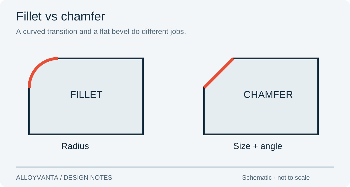
Fillet or chamfer: choose by function
A fillet is a rounded transition; a chamfer is a flat bevel. For a simple edge break, start by considering a chamfer. For a rounded transition required by the part’s function, specify the fillet radius. An internal pocket corner is a separate design problem: a rotating cutter leaves a radius in plan view, and changing the top edge does not remove it.
Put the functional requirement ahead of the appearance. Does the edge guide another part into place, give clearance, sit next to a seal or get handled repeatedly? That answer tells the machinist which geometry must be controlled and which details can remain general.
| Feature | Starting choice | What belongs on the drawing |
|---|---|---|
| General exposed edge | An agreed edge break | Its size or the applicable general note |
| Rounded functional transition | Fillet | Radius and the surfaces it connects |
| Insertion lead-in | Chamfer matched to the mating geometry | Size, angle and any protected sealing area |
| Internal milled pocket corner | Cutter-accessible radius or a reviewed relief | Corner radius and the mating component’s clearance |
A top-edge chamfer does not square a pocket
Imagine a rectangular insert sitting in a milled pocket. The pocket has rounded inside corners, while the insert has sharp outside corners. The insert can touch the corner material before it sits against the intended locating faces. Adding a chamfer around the pocket opening changes the entrance, not the full-depth corner geometry.
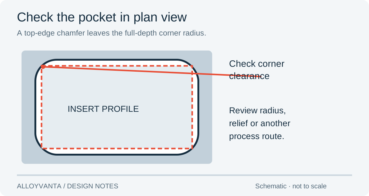
Review three possible routes: round the insert corners, provide a suitable pocket relief, or select another manufacturing operation. Choose the route that preserves the locating faces and available wall thickness. Send the mating-part model when the clearance is difficult to show in one view.
Our recommendation is to resolve the fit in the design before adding a special operation. If the corner has no locating or sealing function, a geometry change may answer the problem more directly. If the corner is functional, identify that reason so the quote evaluates the required route.
Make the callout measurable
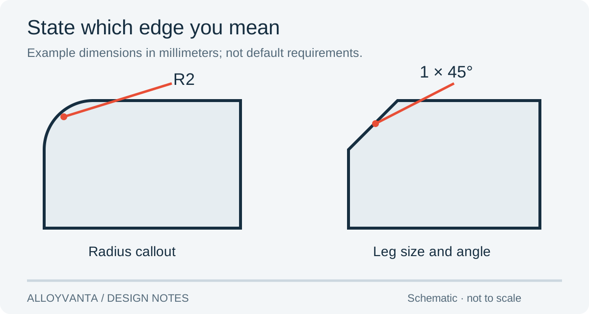
For a fillet, state the radius and point the leader to the relevant transition. For a chamfer, define the geometry through its leg size and angle, or another unambiguous drawing convention. A countersink for a screw head needs the head geometry and specification; “chamfer this hole” leaves that fit unresolved.
| Check | What to resolve |
|---|---|
| Model and PDF | Both describe the same edge and revision |
| Mating component | Clearance includes the corner throughout engagement |
| Finish | Functional limits identify the before/after-finish condition |
| General note | A specific functional edge is not hidden under a general deburr note |
Example: your model has a rounded exterior edge, but the PDF carries a general chamfer note. Mark whether that edge is an exception. Otherwise two reasonable interpretations can produce different parts. A screenshot highlighting the edge helps discussion, while the released model and drawing carry the final decision.
Where the cost difference comes from
Edge geometry affects tool selection, access and toolpath length. An external rounded edge may need a different operation from a straightforward chamfer. Cost still depends on the whole part: a chamfer on an inaccessible face is not automatically the cheaper choice. Protolabs’ edge-design explanation describes why these details change machining work.
Ask for the necessary feature first and identify optional appearance changes separately. A useful quote comparison holds material, quantity and inspection scope constant while evaluating the alternative geometry. It does not compare two parts with different fit requirements as if only the edge style changed.
Frequently asked questions
Is a fillet always stronger than a chamfer?
The result depends on geometry, loading and material. Define the load case and evaluate the functional transition; the feature name alone does not establish strength.
Can every sharp internal corner be milled?
A conventional rotating end mill leaves an internal corner radius. Review clearance, relief or another manufacturing route when the design needs a different corner.
Should every edge have an individual dimension?
Dimension edges with a specific function. Use an agreed general edge treatment for the remaining edges, and clearly mark any exceptions.
Method. The diagrams and design-review situations are explanatory examples, not customer production records.